Note: this document is a complement to the Help page. It is intended to provide more comprehensive information about the fore mention topics. We assume that you have already read the Help page and know the basics of LoopToGo such as creating a Chain.
In LoopToGo, there are many options for routing the different audio and midi signals. The routing is done by choosing and configuring the different Chain types along with IO mappings. At first, it might seem complicated but If you are new to LoopToGo, we suggest that you start with the Standard chains and Master Bus chains. As you become more familiar with the software, you might need more options for routing, especially if you do live performance or work with different studio setups.
Audio and Midi IO mappings
If you are new to LoopToGo, you can skip this section but make sure you will keep in mind that we highly recommend that you use IO mapping. If you don’t configure the mappings, LoopToGo will use the default names for the different IO channels
Audio mappings
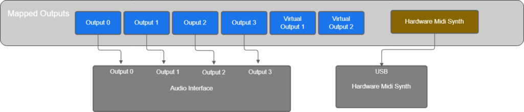
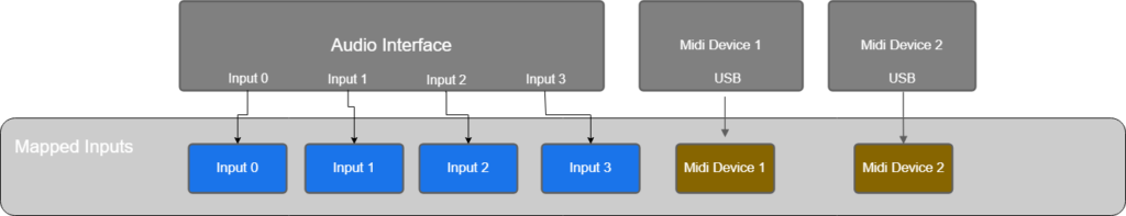
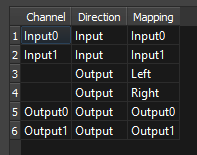
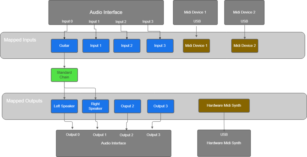
In LoopToGo, to select inputs and outputs for a chain, you choose the Mapped IO. By default, the Mapped IO have the same name as the « physical » IO as shown in the next 2 figures.
In this example, the audio Interface has 4 audio inputs (Input 0 to 3) and 2 input midi devices. Examples of input midi device are keyboards, pedals, drum, controller, etc.
The audio interface has also 4 audio outputs and one output midi device. Examples of output midi device are synthesizer, drums, etc.

Though, it is not mandatory, we strongly suggest that you rename the mapped Inputs and Outputs. There are 2 good reasons for this:
- It is a lot more intuitive to work with names such as « Guitar », « Voice », « Keyboard », « Midi pedal », « Left speaker », « Right speaker », etc. than « Input 0 », « Input 1 », « Output 0 », etc.
- If you change your hardware configuration (Example, plug your guitar in « Input 3 » instead of « Input 1 »), you can just reconfigure the mappings and all your song will be fine. If you don’t use name mappings, you will have to go through all your songs and change the chains IO. Furthermore, if you have different setups with different number of IO, you can use multi-mapping (use more than one mapping for the same Input or Output) and make it easy to switch between the two setups.
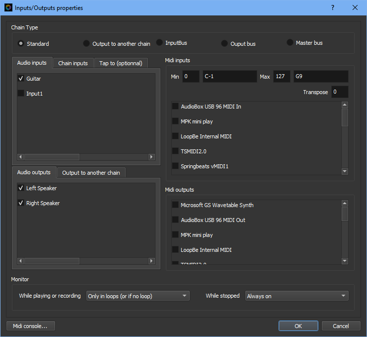
To change Audio IO mappings, go to Files/Preferences/Audio or use shortcut CTR-Coma/Audio. You should have a window similar to this one.
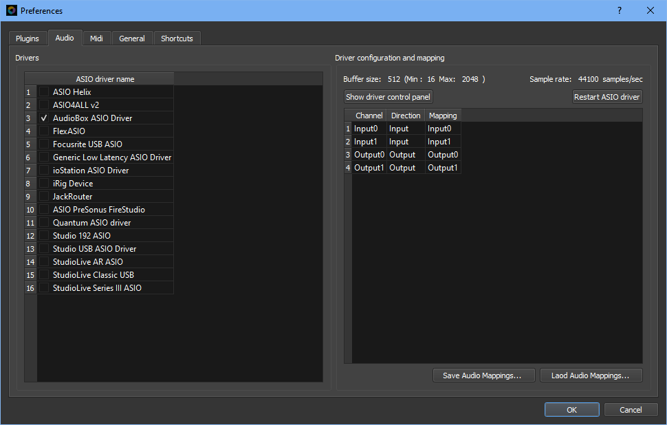
After selecting your Audio interface ASIO driver in the left section, the list of available IO channels will be shown in the right section. To change the mapping name, click on a corresponding line. The following window will appear.
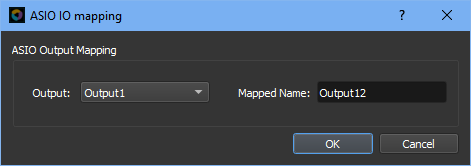
You can type a new Mapped name in the corresponding field. You can also change the channel used. Note that if you first selected an Input Channel, you will only be able to choose another Input Channel and the same applies to Output channels.
To add another mapping on a channel with an existing channel, right click on the corresponding line and select « Add a new mapping ». The same window will allow you to create the new mapping. You can create as many mapping as you want for the same channels
If you want to remove a Mapped name, right click on the corresponding line and select Remove mapping. Note that there should be at least one mapping remaining for each IO channel. If you try to remove the last mapping for a channel, the default mapping for this channel will be created. A default channel mapping can not be removed if it’s the last mapping for this channel.
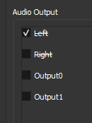
Also, if you remove a mapping that is used in the current song (or among the persistent chains or for the metronome), The channel will be removed but the mapping will still exist. These mappings will be shown struck out in dialogs where you normally select them. See example below. Loading a song that uses mapping that does not exist will also create corresponding mappings with no associated channel. To solve these issues, you have to either choose a channel for these mappings (Files/Preferences/Audio) or select other Inputs/Outputs for the affected chains.
If you work with different hardware setups (home studio, stage, band, gigs, etc.), we suggest that you use the « Save Audio Mappings… » and « Load Audio Mappings… » buttons to switch between different configuration mappings. These buttons are at the right bottom of the Files/Preferences/Audio dialog.
Midi mappings
Midi mappings are very similar to Audio mappings with a few particularities.
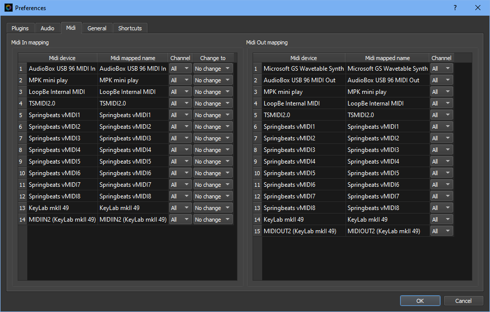
Select Files/Preferences/Midi to configure the midi mappings. Unlike the Audio mapping, there is two sections for Midi mapping. The midi inputs such as keyboards, controller, pads, etc. are listed on the left section and the outputs such as synthesizers, drums, etc. are listed on the rigth.
You can add, edit or remove the mappings in the same way: click on a mapping line to edit it, right-click to add a new one or to remove a mapping.
For each Input mapping, you can specify a Midi channel or select All if you want to receive all midi events from a device. This is very useful to filter events from a device and reduce the number of events recorded and sent to plugins. Say you have a Keyboard with a Pads section, a Keys section and a Controls section. You could set different midi channels for these sections (example: channel 1 for Keys, channel 2 for Knobs and Sliders and channel 10 for the Pads) and then create 3 mappings. See example below:
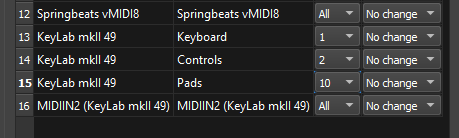
With these mappings, you can ensure that a chain (and its plugins) receives only the events that it needs.
For the midi Input, the column « Change to » is used to change the midi channel of the events to a new channel before sending the events to the plugin. Most plugins do not take into account the midi channel, they just process the events they receive but there are some exceptions. For example, Decent sampler will process a sustains event only if it’s on the same channel as the note on event. Another example where it can be useful to change the midi channel is with the Kontakt Player in which you can have many instruments. The way to control each instrument individually is to assign them different midi channels.
For midi Output, the Column channel is used to set the channel that will be used went sending events to external Midi devices.
Standard Chains
The Standard Chains are the most used in LoopToGo. When you create a Chain, it will be a standard chain by default. A Standard Chain usually has one or two audio inputs and/or one or many midi inputs. It can also have other chains as Input (see « Output to another chain » Chains section for more details). If you select only one output, the Chain is considered to be Mono and if you select two Outputs, the Chain is considered to be Stereo. A Mono chain will have only one audio meter on the console view while a Stereo chain will have two. The figures below show the Chain « Select Audio and Midi IO » dialog and the corresponding routing diagram for this chain.
« Output to another chain » Chains (OTAC Chains)
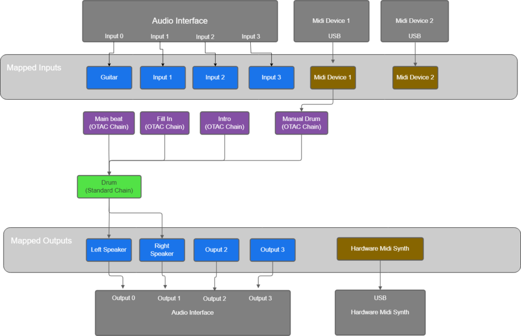
OTAC chains has one or two Audio inputs and/or one or many Midi input and have one or many Standard Chains as outputs. Their main use is to optimize the number of plugins in a song. For example, say you want to program a drum beat, you can use a Sequencer plugin with a drum Plugin on a Standard Chain. If you want some variations in your drum, you could cerate another Standard chain with a Sequencer plugin and a Drum plugin. Then, you want to add some manually recorded drum with another Standard chain and a Drum plugin. You will end up with many Drum plugins which can takes time to load and needs some CPU power. This can be done more efficiently by using OTAC Chains Outputting to a Standard Chain. The Sequencers plugin are put in the OTAC Chains and the Drum plugin is put in the Standard chain. The figure below shows this use case.
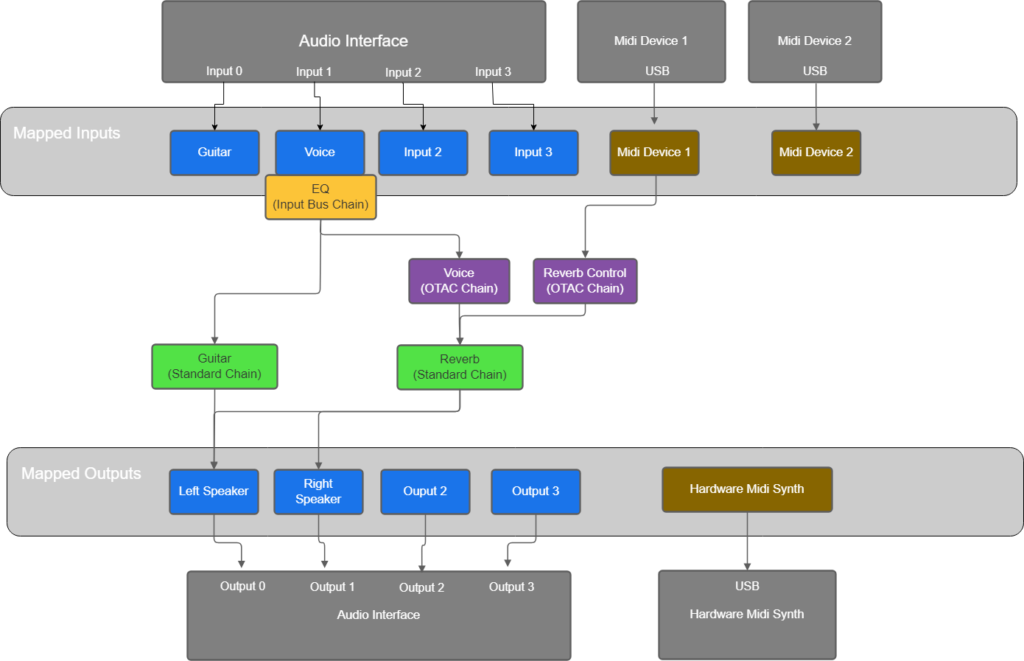
Another use case is when you want to apply the same audio effects to many chains. You can put the audio effects in a Standard chain and create many OTAC chains that will have the standard chain as output. For example, you can have many voice Chain/Track with one Eq and one reverb put in the Standard chain.
Warning: using OTAC with Midi events can lead to undesired results depending of the plugin used. For example, say you have two OTAC chains that send the same note On event to the same plugin and after a while they both send the note Off event. The behavior will depend on how the plugin reacts when receiving many note On events for the same note. Some plugins will keep track of how many note On events they receive and will make sure to turn the sound off only after receiving the same number of midi note Off events. This is the correct behavior. However, some plugins wil turn the sound off at the first note Off event even it received many note On event. This problem does not occur with audio.
Input Bus Chains
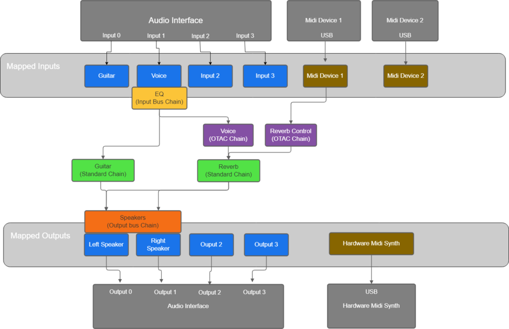
Input bus Chains are inserted immediately after an audio mapped input. Though they can have a midi input (for controlling plugin parameters), they need to have at least one audio input. Once an Input bus Chain is created and active, there is then no way to connect a standard or OTAC chain directly to the mapped Input. All chains that specify the corresponding mapped input as an input will be connected to the Input bus instead. See figure below. This is very handy when a processing (plugin) need to be done for all chain using the same mapped input. For example, if a microphone has too much base and you want to apply an equalizer. Another example would be to use a knob to control the gain of this input.
You can create as many Input Bus Chains as you want for the same mapped input. The order of processing will be the same as the chain in the Console view or the Looper view.
Advanced user tip: for correcting issue related to hardware, is it a better idea to create an Input bus chain as a Persistent chain. By doing that, the correction will be apply to all songs.
Output Bus Chains
Output bus Chains are inserted immediately before an audio mapped output. They can have a midi input (for controlling plugin parameters), but no Audio input. They must have at least one audio output. Once an Output bus Chain is created and active, there is then no way to connect a standard chain directly to the mapped Output. All chains that specify the corresponding mapped output as an output will be connected to the Output bus instead. See figure below. This is very handy when a processing (plugin) need to be done for all chain using the same mapped output. For example, if a speaker set has too much base and you want to apply an equalizer. Another example would be to use a knob to control the gain of this output.
Advanced user tip: for correcting issue related to hardware, is it a better idea to create an Output bus chain as a Persistent chain. By doing that, the correction will be apply to all songs.
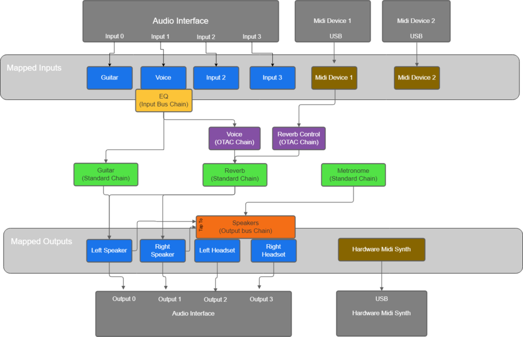
Output bus can also be used to mix mapped outputs with the « Tap to » feature. The signal (other mapped outputs) from the « Tap to » outputs will be added to the signal sent to the mapped outputs. The figure below is an example of how to use the « Tap to » feature to use a metronome plugin with headsets (note that when using LoopToGo metronome, there is another way to do it. See Help page for more details). There is no maximum of « Tap to » signals but you can not tap to the same signal. When there is 2 output selected, there will be two columns shown in the « Tap to » section. The first column will tap to the first output and the second column to the second output.
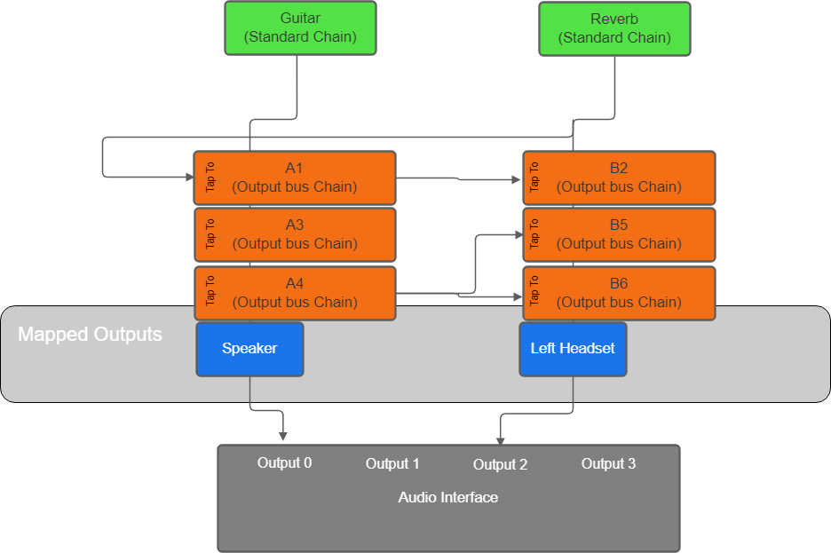
Order of Output buses is very important when using the « Tap To » feature. In the figure below, say the order of Ouput bus is A1, B2, A3, A4, B5 and B6 (the order can be changed by dragging the chains up and down in the Looper View). Now here are the signal for each Output Bus and the overall result for Speaker and Left headset. This example is for showing the routing only, it is not a real use case.
- A1 is tapping to Left Headset: since it’s the first Output bus, it will tap to the output of Reverb. Signal: Guitar + Reverb
- B2 is tapping to Speaker: since A1 is before B2, it will tap after A1. Input Signal: Guitar + A1 Fx + Reverb
- A3 is not tapping. Input Signal: A1 + A1 Fx = Guitar + Reverb + A1 Fx
- A4 is not tapping. Input Signal: A3 + A3 Fx = Guitar + Reverb + A1 Fx + A3 Fx
- B5 is tapping to Speaker: it will tap to A4. Input Signal: B2 + B2 Fx + A4 + A4 Fx = 2 x Guitar + 2 x Reverb + 2 x A1 Fx + A3 Fx + A4 Fx + B2 Fx
- B6 is tapping to Speaker: it will tap to A4. Input signal: B5 + B5 Fx + A4 + A4 Fx = 3 x Guitar + 3 x Reverb + 3 x A1 Fx + 2 x A3 Fx + 2 x A4 Fx + B2 Fx + B5 Fx
- Speaker. Input Signal: A4 + A4 Fx = Guitar + Reverb + A1 Fx + A3 Fx + A4 Fx
- Left headset. Input Signal: B6 + B6 Fx = B5 + B5 Fx + A4 + A4 Fx = 3 x Guitar + 3 x Reverb + 3 x A1 Fx + 2 x A3 Fx + 2 x A4 Fx + B2 Fx + B5 Fx + B6 Fx
Note: before release 1.12.0, Output buses were also used as Master bus but with the possibility to create more than one mapping for the same output (added in 1.12.0), Output buses do not behave as Master bus when there is more than one mapping for the same real output. That’s why Master bus were added in release 1.13.0. Don’t worry, if you don’t use multi-mapping for outputs, Output buses will behave as a Master bus. It is now a good practice to always use « Master Bus » for this purpose.
Master Bus Chains
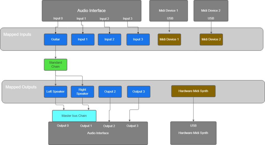
Master bus Chains are inserted immediately before a real audio output. Though they can have a midi input (for controlling plugin parameters), they need to have at least one audio output. To specify the real audio output where the Master bus will be inserted, you have to select a output mapped to this real output. If there is more than one mapping, you can select any of these mapping with the same result. See figure below.
We highly recommend that you create a Master Bus for each real output that are used. It is the best way to detect if there is clipping with the signal you are sending to a real output when you have more than one chain. As a matter of fact, when adding the signal from many chains, it is necessary to avoid clipping (going over 0 dB) or at least to decide how to deal with that before sending the signal to the real Output. Common way to deal with that is by using a limiter plugin or a compressor plugin or to lower the gain. You must know that internally, LoopToGo use floating point numbers so there is no problem with going over 0 dB. The problem occurs when converting the signal to send it to the Audio interface which use Integer numbers with a maximum at 0 dB. Master Bus are placed just before this conversion.
Note: LoopToGo main volume is applied just before the conversion as well and after Master buses if any. Setting the main volume higher than 0 dB can lead to clipping.
Virtual Outputs
Virtual Output is a concept that adds flexibility to your setup. It enables you to route your audio and MIDI tracks to various outputs and then determine how to mix them. For instance, in your home studio, you likely want to route all your tracks to the same stereo monitors. However, when performing in front of a large audience with a dedicated audio engineer, you might prefer sending different signals (voice, drums, guitar, etc.) to the main console, allowing the engineer to tailor the mix to the room’s acoustics. To achieve this, you’ll need an audio interface that supports multiple outputs. Perhaps you plan to borrow or purchase one for your upcoming performance, but in your home studio, you only have two outputs. Using Virtual Outputs, you can prepare your setup as if you had as many outputs as needed. Then, when you have access to such an interface, the configuration becomes straightforward; simply employ a different mapping configuration or utilize different persistent chains.